How to Build a Continuity Tester
If you are looking for a simple circuit for test continuity of wires and long conductors, the explained 4 circuits are the ones which you can try and might fulfill your requirement.
What is a Continuity Tester
A continuity tester is a device which is used for identifying the correct continuity of a particular conductor in question. Or in other words the device may be used for tracing faults or breaks in a particular conductor or a wire.
The device is actually a simple LED and a cell circuit, where the LED is made to switch by passing the cell voltage to the LED via the conductor in question.
If the conductor is not broken, the cell voltage circulates through it and reaches the LED to complete the circuit and in the course illuminates the LED, providing the relevant information.
If the conductor is open internally, the cell voltage is unable to complete the circuit and the LED remains shut OFF, indicating the fault.
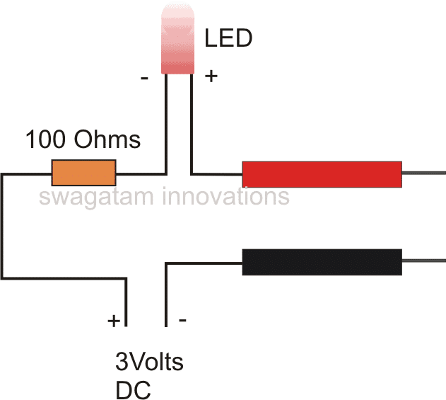
1) Using One LED and Resistor
The first circuit diagram shows a very simple continuity circuit where only a LED/resistor set up along with a 3 volt source is used.
The prods are connected across the ends of the wires or the conductor which needs to be checked. The results regarding the status of the wire is achieved as explained above.
However this circuit is quite crude and won't be able to check big cable networks where the fed voltage may drop substantially in the path and might fail to illuminate the LED properly.
For checking complex and large wire or cable bundles, rather a much sensitive circuit may be required.
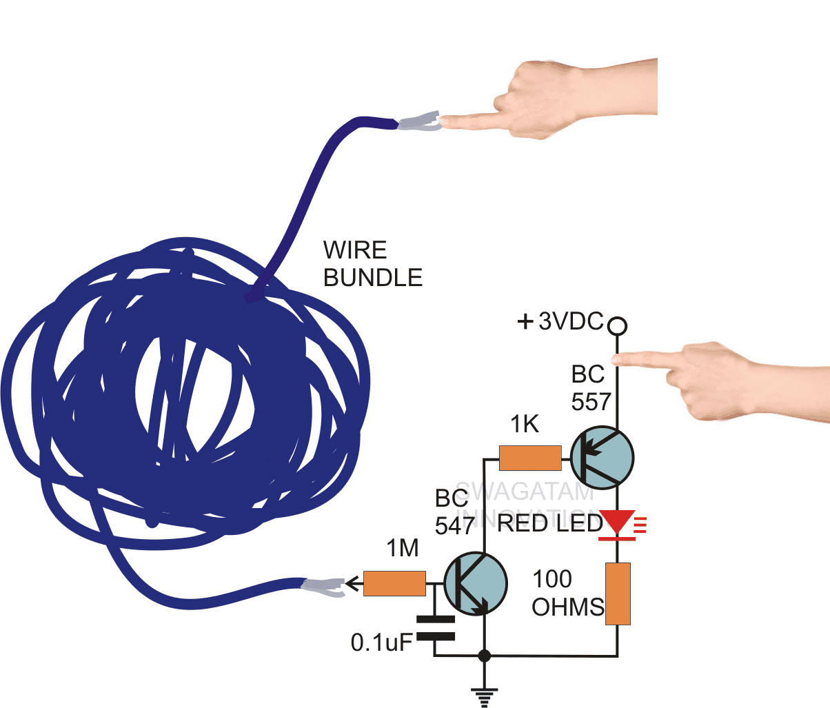
2) Using Two Transistors
The next circuit shows a configuration which is much rugged and highly sensitive.
Moreover the wire ends may be checked via finger touches, which simply avoids th need of lengthy prods from the continuity tester.
The circuit employs a couple of cheap hi-gain transistors which are coupled together in such a way that the over all gain of the circuit becomes very high.
Even a few milli volts is enough for making the circuit conduct and illuminate the LED.
The connections can be seen in the figure, how through easy finger touch operations, even the staus of big wire bundles may be identified in seconds.
If the wire bundle is without breaks, the LED lights up brightly, and in case the wire is open somewhere, keeps the LED completely shut OFF.
This sensitive circuit can also be used as a line tester, the 3volt point is held with hand, and the 1M end is touched to the point where the LINE presence needs to be tested.
The presence of phase, lights up the LED and vice versa.
Video Demonstration
3) Using LM3909
The following miniature tester is built using just 4 inexpensive components, and operated from a AAA 1.5 V dry cell. It can be used for testing continuity tests across wiring harnesses and on circuit networks, through appropriate test prods hooked up to points A and B.
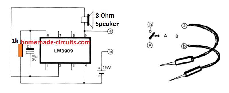
After some trial and error effort, you will be able to perfectly judge the contact resistance by comparing the differences in the level of the sound frequency. Another great application of this unit could be in the form of a mini siren or simply as a morse code practice which can be done by connecting a morse key between A and B.
4) Simple Continuity Tester Circuit using IC 555
In the following second project learn how to make a simple continuity checker circuit using 555 timer. And what makes this circuit so special is that no transistor is used in it and hence this is indeed the simplest continuity checker.
By Ankit Negi
We all know the importance of 555 TIMER in electronics.
The fact that they are used even today, 45 years after their first appearance in electronics industry makes it a key component of our day to day circuit.
There's hardly anything this 555 timer cannot do for you. From using it as a clock generator to voltage regulator. And so here we are, making yet another very useful circuit using this invincible IC.
As we already know a continuity checker is a simple electronic tool that checks the continuity between two terminals of a circuit. For let's say you have a wire, which you want to check for continuity.
So you have to just connect its two terminal to the continuity checker and if there's no break in the circuit it will indicate it( either by a glowing led or buzzer) and if there's break than nothing will happen.
COMPONENTS REQUIRED:
1. A 555 timer
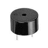
2. One buzzer ( **if you do not have buzzer then use LED)
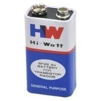
3. 9v battery
4. One 4.7 k resistor
5. One 47 k resistor
6. One 10uf ceramic capacitor
7. One 0.1 uf ceramic capacitor
8. Two connecting probes( red and black)
Circuit diagram:
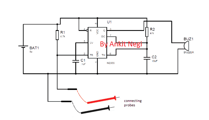
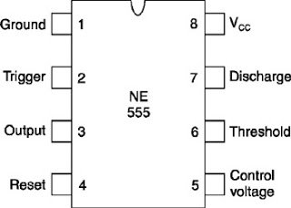
There are total 8 pins in 555 timer as shown in circuit diagram make connections as shown and don't forget to connect capacitors as they are as important as any other components in this circuit.
Connecting probes are connected between trigger terminal (2) and ground.
**If you do not have a buzzer than connect led in series with 1k resistor in place of buzzer**
CIRCUIT WORKING:
Before I explain its working you must know these two points:
A. If voltage at trigger pin is less than 1/3v of the applied voltage (9v in this case), only than the output will be 1(HIGH).
B. If voltage at threshold pin is greater than 2/3v of the applied voltage then the capacitor (10 uf) starts discharging through discharge pin (7th) to ground.
As you can see in the above iC 555 based continuity tester circuit, to check continuity you place the circuit between probes (connected to trigger terminal and ground).
Case1—if there is a break in circuit
If this case arises then that means there is infinite resistance(open circuit) between pin 2 and ground which causes all voltage drop between pin 2 and ground which is obviously greater than 1/3 of 9 volt, hence(from point 1) we get 0 volt as output from pin 3 at which buzzer or led is connected. Hence buzzer will produce no sound indicating a break in circuit.
Case2—if there is no break in circuit
If this case arises then that means there is almost 0 volts (short circuit) between pin 2 and ground which causes all voltage drop across 4.7k resistor and thus pin 2 get 0 volt which is obviously less than 1/3 of 9 volt, hence(from point 1) we get 1 volt as output from pin 3 at which buzzer is connected. Hence buzzer will produce sound indicating continuity in circuit.
Enhanced Continuity Tester Circuit
You might be thinking you are obtaining a perfect reading on the meter and afterward surprised to discover that you had been in fact looking across a coil or low resistance system? The proposed enhanced super continuity tester circuit specifically can be a time saver which handles this type of situations, and can additionally verify resistances as high as around 150k.
How it Works
As shown in the figure, a reference voltage (as determined by the potentiometer R1) is put on the inverting input of the IC (1/4th of an LM339 quad comparator).
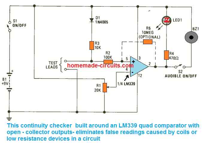
Potentiometer R1 could be a trimmer type variable resistor, in case you intend to make use of the device for continuity tests, R1 must be a multi-turn type for simplicity of adjustment. The relationship to be examined is placed across the test probes and to ground, and across the junction of R2 and R3.
Parts R3 and D1 safeguard against unintentional application of voltage to the circuit. Considering that the non-inverting input possesses a high impedance, the intersection of R3 is almost just like the non-inverting input so far as proportions are involved.
Once the voltage at the non-inverting input of U1 at pin 5 drops under that at the inverting input, the output becomes low. This leads to the buzzer becoming active and sounding, showing continuity. Potentiometer R1 adjusts the limit where the buzzer gets triggered and sounds. When resistance is detected across the R2 /R3 junction and ground, a voltage divider is created, and this is referenced to the voltage divider established by potentiometer R1.
In case the resistance is very small in comparison to the R1 value adjustment, the buzzer starts making noise.
How to Calibrate
In order to scale and calibrate the tester, you will need a couple of resistors; 100 ohms and 120 ohms. Hook up the 100 ohm resistor across the test probes and start tweaking R1 until the buzzer starts making noise.
Next, hook up the 120 ohm resistor and ensure the buzzer remains perfetly silent. The continuity tester is at this point fixed at examine any resistance below 100 ohms. None of the components values are critical, and neither is the battery voltage because the comparator is configured for voltage ratios only and not specific values.
Smart Continuity Tester
The majority of continuity testers currently available are susceptible to false results. They won't show wrong results intentionally, yet when they find a smallish resistance, they are going to still show you that there's probably a continuity. The following continuity tester unit takes a different approach. In case there is continuity, it is going to inform you about the same.
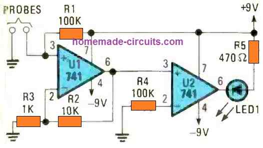
But during a low resistance via an electronic component, the circuit can confirm that too without fail. Referring to the figure above, we find the circuit makes use of a couple of 741 opamps. It provides a short-circuit test current of lower than 200uA. It picks up resistance values of lower than 10 ohms. Sweetest of all, it will never malfunction when it comes across PN junction or a diode.
Source: https://www.homemade-circuits.com/make-this-simplest-continuity-tester/
0 Response to "How to Build a Continuity Tester"
Post a Comment